Sunday 30 September 2012

Week 9

Title of Activity

Continue Programming from last week.

Objective
-Troubleshoot the program.
-Searching the solution in website arduino and forum.

Content/Procedure


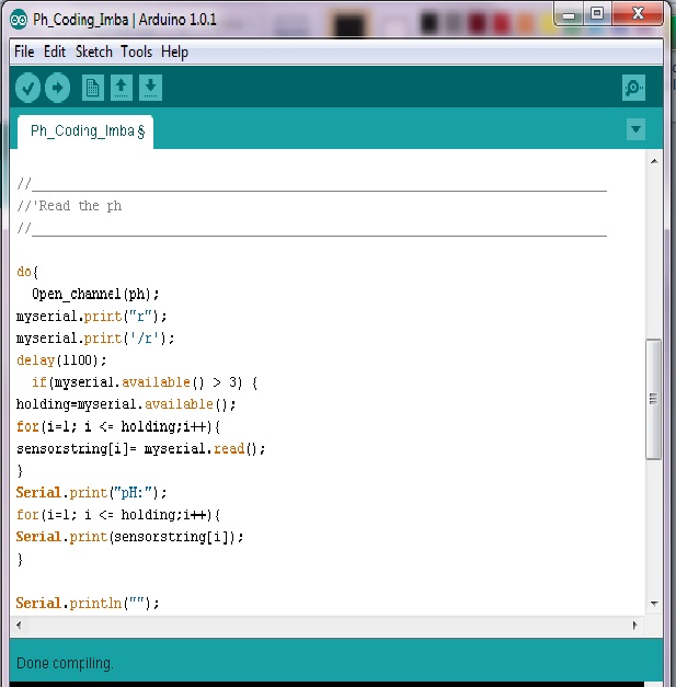
My previously problem is "a function-definition is not allowed here before }" that make strugglin to find the solution in their web support.


So, I find the related same problem with my problem. Then i try used that advice to fix my problem.
 
I try to changed the rx and fx input as my program. Unfortunately the problem still have and it can't be solve it right. I should to do more research and find the solution as fast than i can to proceed my next programming.


Result/Analysis
Still that have some error that can't be read. That error  it detect "a function-definition is not allowed here before }". Try to do more research to counter my program in this week.

Conclusion
Some basic in writing a program because they are some command we should able to understand, if have no basic about programming it can cause your trouble and stuck.. For this problem i do more research and reading a arduino language style program.

Saturday 22 September 2012

Week 8


Title of Activity

Programming For My Project (Arduino Software)

Objective
-Write the program that been used in my project.
-Testing the program.

Content/Procedure

Using the latest arduino software (1.0.1)

Select the arduino board . For this project i use Arduino Uno

Select the type of programmer, in this I use AVRISP mkII or it automatic default with that type programmer.

Select serial port for arduino, for my arduino it COM9. Each arduino have different serial port, it like ID for arduino.


Result/Analysis
After compiling the program that have some error that can't be read. For this error  it detect "a function-definition is not allowed here before }". It mean that some of this function couldn't be read so should checking the coding that what I miss.

Conclusion
Programming is the one of challenging part, we should have some basic in writing a program because they are some command we should able to understand, if have no basic about programming it can cause your trouble and stuck. So, we should well prepare to face any problem that accouter in writing a program. For this problem i do more research and reading a arduino language style program.

Saturday 15 September 2012

Week 7


Title of Activity

Soldering

Objective
- Soldering all the component on PCB board

Content/Procedure

Before start soldering, the equipment that should we have is
- Solder iron
- Solder lead


Solder iron and solder lead

Use the appropriate solder point because we soldering component.


Keep temperature as low as possible while maintaining enough temperature to quickly solder a joint (around 2 or 3 second)

The pcb look like after all component been solder.

My pcb after done soldering with component.


Conclusion

Soldering is accomplished by quickly heating the component to be joined, and then applying a flux and a solder to the mating surfaces. The finished solder joint forming an excellent electrical connection between wires and a strong mechanical joint between the metal parts. Care don't soldering too long it can cause board become (OC) open circuit, and some of component is can't stand heat resistance when soldering.

Sunday 9 September 2012

Week 6


Title of Activity

Drilling and check the component leg it matching on board


Objective
- Drill pcb holes.
- Check if the holes is matching with component leg.

Content/Procedure

Before starting drill pcb hole, we should use the drill bits size 0.5mm that matching to all components leg.
The drill and pcb should be 90 degree to prevent components legs bents.

Check it if the holes is matching with components leg.
Done the pcb hole is matching with components leg.

The pcb board look like  after drilling

Result/Analysis

- Your should drill it slow to prevent cuprum damage or eroding
- Check each time finish drill a hole for the component leg so as not to avoid make the hole wide completely.


Conclusion

This is one another step that should be done while finish etching. This one soft skill that has been learn, later on we should soldering the components. We should pay attention to when doing drillling so if have mistaken even one hole it has spoiled all the circuit.

Sunday 2 September 2012

Week 5
Title of Activity

Design Circuit Using Fritzing (Schematic) & DipTrace(PCB) (Continue)


Objective
- Continue my previously.
- Etching process

Content/Procedure
Desing on Diptrace software for PCB board.
After done design the circuit, print it on OHP paper for next step for making PCB.
PCB desing on Diptrace software
After printed on OHP paper paste it on PCB board that has been measured that suitable size.

Use iron to make it paste on pcb. Remember to cover it with something suitable to OHP paper because it a easy to  meltdown.

This process take about 30minutes.

After done ironing, make sure it cool down before remove the OHP paper.

Soak it in acid solution so that the copper is not required eroded. This process takes about 30 minutes, it should be reminded to always see every 5 minutes so it does not erode the circuit

After that clean it with flowing water to clean it from acid solution


Use tinker to remove printed that not been remove by acid with turpentine that left only the circuit design.


Result/Analysis

Problem Statement
1) Too many point that need to need connected but with limited space on PCB.
2) The printed circuit  not attached smoothly on PCB board because not properly iron.
Solution
1) Use female and male connected as a wired jumper for solution.
2) Reprinted it on OHP paper and ironing it wisely and properly.

Conclusion
All the processes involved in the making safely circuit have completed with care and precision. All this process should be done carefully so that the circuit is not damaged and eroded, if this happens all done back from the printing process until the last process that has been shown.